Sine Wave Converter
Sine Wave Converter Circuit
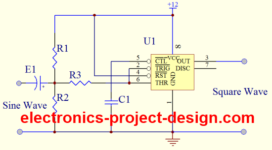
This Sine Wave Converter is implemented using a 555 Timer integrated circuit configured as a Schmitt trigger. By connecting trigger input pin 2 and threshold input pin 6 of the timer together while applying the input sine wave signal, output square wave will be obtained. In this circuit, a 12V DC supply is used.
This is achieved because once the input signal is above 2/3 X 12V = 8V DC, the output 3 voltage will become low (< 1V DC). The output voltage will remain low until the input signal go down to below 1/3 X 12V = 4V DC. When this threshold is achieved, the output will go high (>10V DC).
It will remain high until the input signal voltage level reaches 8V when it will switch back to low. This type of switching continues on hence by applying a sine wave input, you will get a square wave output.

The difference of voltage 8V-4V is 4V which is the hysteresis. This hysteresis value is necessary to ensure proper signal conditioning in the presence of electrical noises in the circuit.
The capacitor E1 is used to remove the DC component of the input signal that may be present. Resistors R1 and R2 are used as voltage divider to divide the quiescent voltage of 6V.
There are many instances where you will need to convert a sine wave signal to square wave signal as many input ports of semiconductor devices are triggered by rising or falling of clock signal.
Getting an oscilloscope will be helpful to get a better understanding of this circuit and for trouble shooting purposes. If you do not have one, connect the output to a LED and resistor as a rough visual indicator that the circuit is working fine.
Parts List
| Label | Description |
| R1, R2 | 110K ohm 5% 1/4W Carbon Film Resistor |
| R3 | 4.7K ohm 5% 1/4W Carbon Film Resistor |
| C1 | 0.01uF/25V Ceramic Capacitor |
| E1 | 1uF/25V Electrolytic Capacitor |
| U1 | 555 Timer IC |
Back To Sine Wave Converter Home Page


New! Comments
Have your say about what you just read! Leave us a comment in the box below.