Operational Amplifier
The Operational Amplifier is a differential amplifier having a large voltage gain, very high input impedance and low output impedance. It has a "inverting" (-) input which is out of phase with the output and "non-inverting" (+) input which is in phase with the output and a single output. It is usually powered by a dual polarity power supply in the range of +/- 5V to +/- 15V.
It is widely used because it approach an ideal amplifiers especially for DC and low frequency signals. The ideal op-amp has an infinite input impedance so that it can be connected to any signal source with no loading effects.
An op amp such as 741 has an input impedance of 6 Mohm. Another of its ideal characteristics is its infinite gain. Standard op amp provide over 100 dB of gain at low frequencies. It also would infinitely reject common mode signals.
CMRR ranges from 90 dB to 130 dB. The ideal amplifier has zero output impedance and is able to drive any load. The ideal amplifier also has infinite bandwidth meaning that it can amplify any signal frequency In this area, the actual op amp falls short of the ideal, with useful gain extending only into tens of kHz to kHz region. Modern amplifier approach the ideal close enough to make them useful in many applications.
Common Types of Applications
Inverting Amplifier

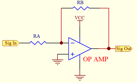
The operational amplifier is connected using two resistors RA and RB such that the input signal is applied in series with RA and the output is connected back to the inverting input through RB. The non-inverting input is connected to the ground reference.
As the input signal moves positive, the output will move negative and vice versa. The amount of voltage change at the output relative to the input depends on the ratio of the two resistors RA and RB. As the input moves in one direction, the output will move in the opposite direction such that the voltage at the inverting input is zero volts in this case.
If RA is 1K and RB is 10K and the input is +0.5V volt then there will be 0.5 mA of current flowing through RA and the output will have to move to -5 volts to supply the same current through RB and keep the voltage at the inverting input at zero. The voltage gain in this case would be RB/RA or 10K/1K = 10.
Note that since the voltage at the inverting input is always zero, the input signal will see a input impedance equal to RA, or 1K in this case. For higher input impedances, both resistor values can be increased.
The output voltage is Vout = -Vin(RB/RA)
Noninverting Operational Amplifier

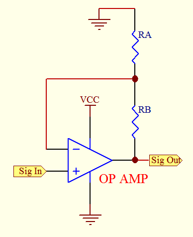
The noninverting amplifier is connected so that the input signal goes directly to the noninverting input (+) and the input resistor RA is grounded. In this configuration, the input impedance as seen by the signal is much greater since the input will be following the applied signal and not held constant by the feedback current.
As the signal moves in either direction, the output will follow in phase to maintain the inverting input at the same voltage as the input (+).
The operational amplifier output voltage is Vout = Vin(1 + RB/RA)
Operational Amplifier Voltage Follower

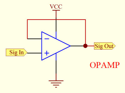
The voltage follower, also called a buffer, provides a high input impedance, a low output impedance, and unity gain. As the input voltage changes, the output and inverting input will change by an equal amount. The voltage gain of this configuration is unity or 1.
This circuit is useful though it does not have any voltage gain. Since it has a high input impedance, it makes an excellent isolation amplifier. The inverting amplifier exhibits a much lower input impedance due to the virtual ground created by the negative feedback.
A high impedance signal source will suffer loading effects when connected to such amplifier and therefore it is sometimes necessary to isolate the signal source by connecting it to a voltage follower to the next stage.
Back To Operational Amplifier Home Page


New! Comments
Have your say about what you just read! Leave us a comment in the box below.