Educational Game
This educational game project can be used in a quiz competition to see which of the participants press the button first to answer questions posed by the quiz master. This constructional project is based on a latch CD74HC75 IC and a 4 input CD74AC20 NAND IC. The first person to press the switch will light up the LED designated for the person. The rest of the LEDs will not be able to be activated until the RESET button is pressed.
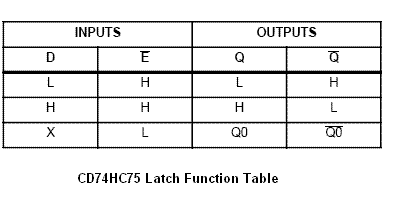
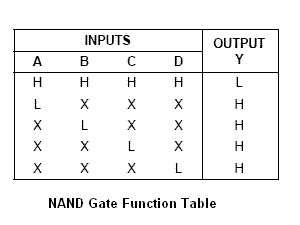
The truth table of the Latch IC and the NAND IC is as shown in the figures below.


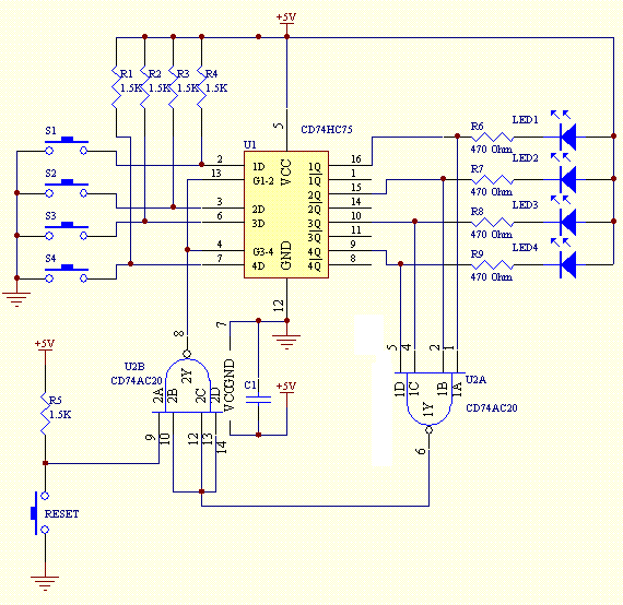
Schematic Diagram

Initially when RESET button is pressed, the output of NAND gate from U2A will be logic "0" as all the inputs are at logic "1"state. As shown in the truth table for NAND gate, when all the inputs are "1", its output will be "0". Hence the output of NAND gate from U2B will be logic "1" since an input of "0" will cause it to go to logic "1". The logic "1" to the latch indicates that it is ready to output any data once any of the button is pushed.
If the first button pushed is S1, the logic at its output 1Q will be logic "0" and caused LED1 to light up. At the same time,it caused the output of U2A to go into logic "1". Hence the output of U2B will be logic "0" causing the latch to be disable which means that the outputs of all the latches will be at their previous state. As a result, the player who pressed button S1 will be shown as the one who is first to press the button and so qualify to answer the question.
The RESET button will be pressed by the quiz master to prepare the circuit for the next game.
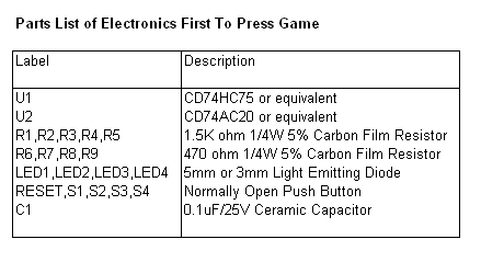
Parts List

Electronics Educational Game Home Page


New! Comments
Have your say about what you just read! Leave us a comment in the box below.